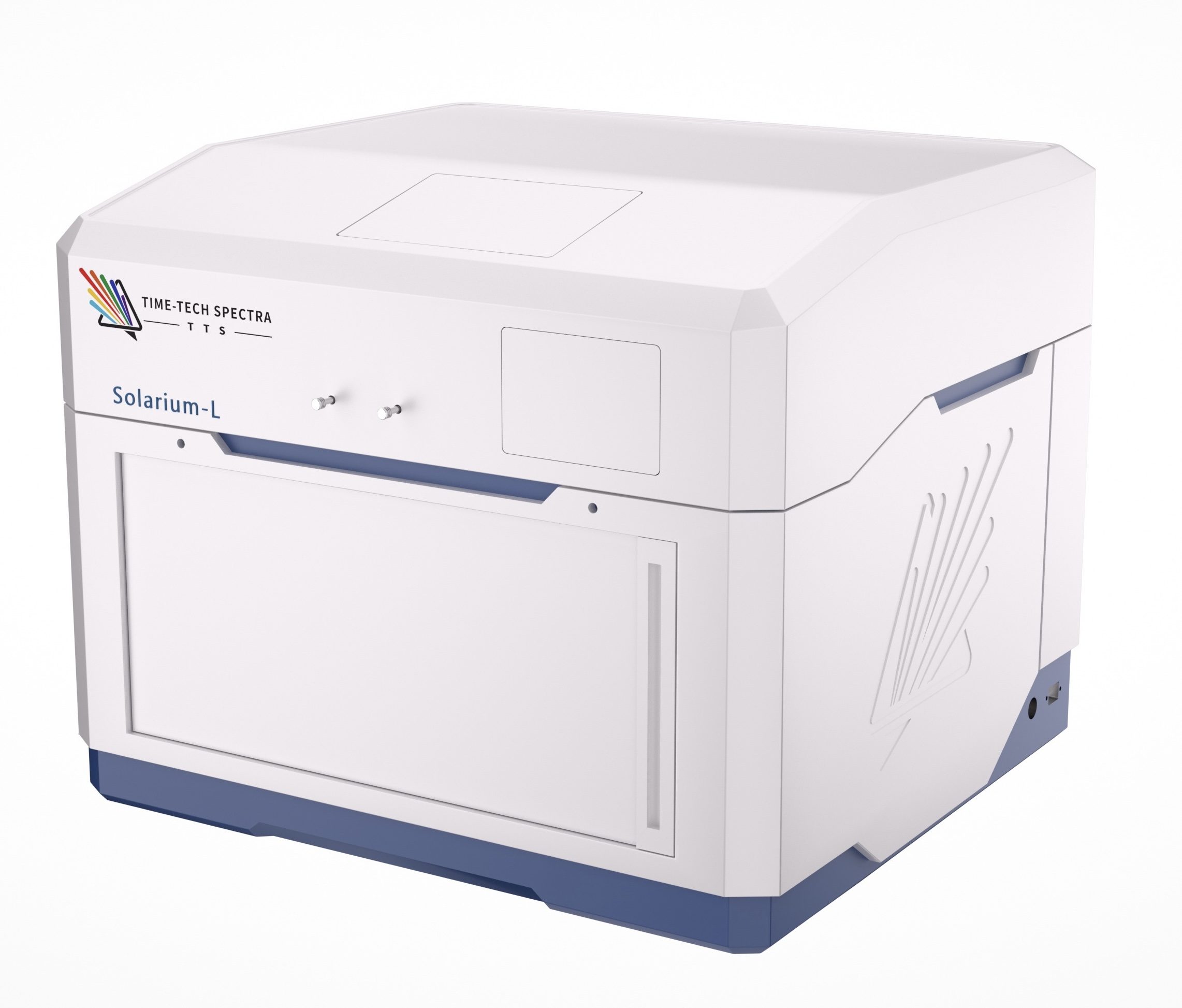
Combine luminescence imaging with photovoltaic characterisation. Solarium-L supports configurable measurements of films, single-junction cells and silicon-perovskite tandem devices.
Is Solarium-L right for your experiment?
For research linking spatial optical variation with photovoltaic properties, from material screening to device analysis.
Manufacturer-listed values below distinguish the measurement parameter from its configuration conditions. The final quotation defines the supplied system.
Solarium-L specification guide
Parameter
Published value / capability
Configuration condition
Supported sample types
Silicon, perovskite and silicon-perovskite tandem cells; thin films
Measurement functions depend on sample and configuration.
Optical measurements
PL/EL intensity, spectra, TRPL and luminescence-derived analysis
Specify PLQE, QFLS and pseudo-J-V workflows explicitly.
Standard LED wavelengths
450 and 850 nm
Other listed choices include 532 and 900 nm.
LED intensity range
0.01-1.5 suns
Confirm calibration, uniformity and sample-plane conditions.
Picosecond laser choices
405, 450, 532, 780, 808 or 850 nm
Selectable excitation; availability depends on the measurement path.
Maximum single wide-field image
≤2 × 2 cm²
Not the field of view at every spatial resolution or in confocal mode.
Spectral resolution
0.14 nm
300 mm monochromator, 1200 grooves/mm grating and 25 μm CCD pixel size.
Minimum spectrum acquisition
5 ms
Spectrum acquisition, not a complete lifetime or mapping experiment.
Confocal resolution
Up to 260 nm
100× oil-immersion configuration.
TCSPC module
IRF ≤230 ps; APD range 400-1100 nm
Module configuration lists 375/405 nm picosecond excitation; confirm compatibility with other sources.
Wide-field imaging, confocal imaging and electrical characterisation have different configuration requirements. Do not assume maximum field of view, finest resolution and every output are obtained simultaneously.
Select the options needed for your measurement; listed choices are not automatically included.
Wide-field or confocal imaging
Choose spatial coverage and detail around the sample rather than specifying only the maximum image size.
Wide-field or confocal imaging configuration
Wide-field tandem modes
Supplier lists 1.5 μm/pixel with area <7 mm² or 8 μm/pixel with area <80 mm².
Confocal
Objective and scanning configuration for local PL spectra, PLQE and QFLS measurements.
Electrical characterisation
Select contact and bias arrangements for the required photovoltaic outputs.
Electrical characterisation configuration
Direct measurements
True J-V, photocurrent and photovoltage require the corresponding device interfaces.
Luminescence-derived outputs
Pseudo-J-V and related maps depend on the measurement protocol, calibration and model assumptions; they are not simply direct electrical J-V data.
Illumination & environment
Specify excitation, sample scanning and any environment accessories.
Illumination & environment configuration
Illumination
LED and picosecond laser choices; confirm wavelength, power and calibrated intensity at the sample.
Environment
High-voltage and low-temperature compatibility must be assessed for the selected sample and stage.
Measurement examples
Original Time-Tech Spectra figures, not HX measurements. Axes, scales and plotted data are retained. Example performance depends on the sample and acquisition conditions.
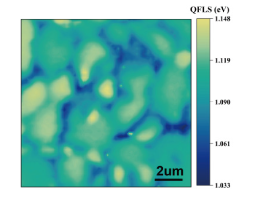
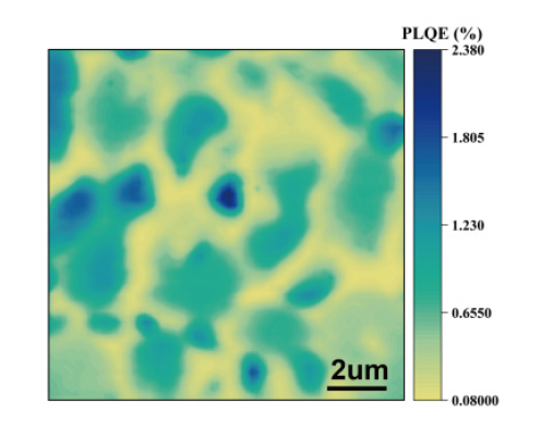
Perovskite film · QFLS and luminescence yield
The maps show two different outputs: quasi-Fermi-level splitting (QFLS) and photoluminescence yield. Compare spatial variation using a defined excitation and calibration procedure.
Perovskite film. Excitation wavelength, fluence and calibration details are not supplied with these web figures; request the complete measurement conditions before quantitative comparison.
Provide cell architecture, dimensions, active area and contact layout. State whether the sample is a film, single-junction or tandem device.
Measurement priorities
Identify the required outputs and whether you need local imaging, whole-area screening, direct electrical measurements or luminescence-derived analysis.
Calibration & installation
Agree on intensity/spectral calibration, reference samples, bias limits, environmental requirements and the installed footprint before ordering.
Selection questions
What do PLQE and QFLS mean?
PLQE refers to photoluminescence quantum efficiency; QFLS is quasi-Fermi-level splitting. Both require a defined measurement and analysis protocol. Specify the quantity, calibration and operating conditions rather than comparing labels alone.
Is pseudo-J-V the same as an electrical J-V sweep?
No. A pseudo-J-V result is inferred using a luminescence-based protocol and assumptions. Direct J-V measures electrical current and voltage. Define which result is needed and configure the system accordingly.