
Microscope imaging & digital inspection
Upgrade an existing microscope, inspect a component on screen, or compare two specimens. Start with the task and the smallest feature you need to see.
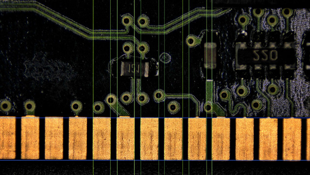
One imaging task, three possible routes
A camera upgrade retains your microscope optics. A digital microscope provides an integrated inspection workspace. A comparison microscope adds independent positioning and imaging for two physical specimens.
Image: OSTEC CE210T brochure example. It illustrates software tools, not independently verified dimensional accuracy.
What do you need to do?
| Your task | Starting point | Key selection question |
|---|---|---|
| Document or share an existing microscope view | KoPa Microscope Cameras | Which optical port, adapter and viewing device will you use? |
| Inspect components and record visible features | CE210T 4K Digital Microscope | Will the field of view, working distance and lighting suit the part? |
| Examine corresponding features on two specimens | KoPa Digital Comparison Microscope | Do you need independent stages and live views of both specimens? |
1. Add imaging to an existing microscope
For teaching, image documentation and shared viewing, a camera can retain an existing microscope and its objectives. Identify the microscope model, head and photo port before choosing a camera: a connector alone does not confirm optical coverage or mechanical fit.
Use your own device
A WiFi-camera workflow uses supported computer or mobile software. Check connection options, live-view speed and the laboratory's network policy.
Build a PC-free workstation
A Smart camera provides an embedded imaging workspace and uses a separate display. Confirm the monitor connection and whether the display is included.
Keep the screen together
A Smart Display camera combines the viewing screen and camera. Check clearance around the microscope head and the operator's working position.
For calibrated measurements, validate the scale for the objective and adapter combination. Higher pixel count alone does not establish greater optical resolution or measurement accuracy.
Compare camera workflows →2. Inspect electronics and small components
Connectors, assembled boards and small-part surfaces call for sufficient working space and controllable illumination. Define whether the task is visual checking, measurement, recording or comparison with a reference image.
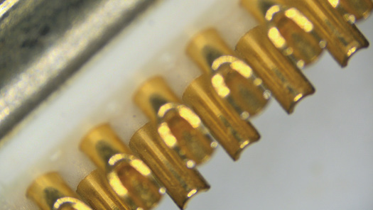
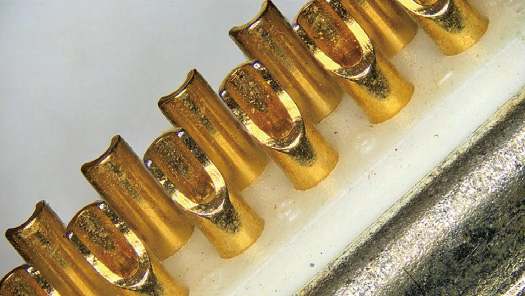
The CE210T Option B lists a 120 mm working distance and optical zoom from 0.3x to 1.8x. Check both the whole-part field of view and the smallest feature; test glare and contrast on a representative surface before defining an inspection method.
Specify accuracy and repeatability requirements separately from camera resolution. A visual inspection example is not a metrology certificate or an automated pass/fail capability.
See CE210T inspection examples →3. Compare two specimens or a stored reference
Comparing a live image with a stored reference may be sufficient for routine component checks. When two physical specimens must be independently aligned and examined, a dedicated comparison microscope provides separate imaging paths and stages.
The KoPa BD20 Series III supports paired-image alignment, overlap and stored-image comparison. Its documented cylindrical-surface function produces an unwrapped view; the appropriate holder, rotation arrangement and software configuration must be confirmed for your sample.
- Match the relevant features, magnification and lighting before comparing.
- Keep acquisition conditions and reference-image provenance with the observations.
- Confirm specimen access, mounting and reporting requirements before selecting accessories.
Visual similarity alone does not establish identity, authenticity or a forensic conclusion. Use a validated method appropriate to your laboratory.
See comparison-microscope examples →Plan the setup with HX Technology
Bring a representative sample or share clear photos together with these details:
- Sample material, dimensions, height and smallest feature of interest.
- Existing microscope model, objective and camera-port photos, if applicable.
- Viewing, measurement, recording or comparison task.
- Preferred screen, computer and network arrangement.
- Required accuracy, reporting format and any validation requirements.
Product examples are based on OSTEC's camera brochures, CE210T Option B information and BD20 Series III information. Final suitability and supplied configuration require confirmation.